Blog

  • Understanding the 12V 24V DC Automotive Relay: A Comprehensive Guide

      The 12V 24V DC Automotive Relay is a crucial component in modern vehicles, playing a vital role in the operation of various electrical systems. This article aims to provide a comprehensive guide to understanding the 12V 24V DC Automotive Relay, its functions, types, and applications.

      **Introduction**

      Automotive relays are essential for controlling high-current electrical systems in vehicles. These relays act as switches, allowing low-current signals from the vehicle’s electrical system to control high-current circuits. The 12V 24V DC Automotive Relay is designed to handle voltages ranging from 12V to 24V, making it suitable for a wide range of vehicles.

      **Functions of 12V 24V DC Automotive Relay**

      The primary function of a 12V 24V DC Automotive Relay is to switch high-current circuits on and off based on low-current signals from the vehicle’s electrical system. This allows the driver or the vehicle’s computer system to control high-power devices such as the engine starter, power windows, and headlights.

      **Types of 12V 24V DC Automotive Relay**

      There are several types of 12V 24V DC Automotive Relays, each designed for specific applications:

      1. **Single-Channel Relay**: This type of relay has one input and one output, making it suitable for controlling a single high-power device.
    2. **Double-Channel Relay**: A double-channel relay has two inputs and two outputs, allowing it to control two separate high-power devices simultaneously.
    3. **Multi-Channel Relay**: Multi-channel relays have more than two inputs and outputs, making them suitable for complex electrical systems with multiple high-power devices.

      **Applications of 12V 24V DC Automotive Relay**

      The 12V 24V DC Automotive Relay is used in various applications within a vehicle, including:

      1. **Engine Management System**: The relay is used to control the fuel injectors, ignition coils, and other components in the engine management system.
    2. **Starter Motor**: The relay is used to control the high-current circuit that powers the starter motor, allowing the engine to start.
    3. **Power Windows and Seats**: The relay is used to control the high-current circuit that powers the motors for power windows and seats.
    4. **Headlights and Taillights**: The relay is used to switch the high-current circuit that powers the headlights and taillights.

      **Installation and Maintenance**

      When installing a 12V 24V DC Automotive Relay, it is essential to ensure that it is compatible with the vehicle’s electrical system. This involves checking the relay’s voltage, current, and contact ratings.

      Regular maintenance of the relay is also crucial to ensure its proper functioning. This includes checking for signs of wear and tear, such as corrosion on the contacts, and replacing the relay if necessary.

      **Conclusion**

      The 12V 24V DC Automotive Relay is a critical component in modern vehicles, playing a vital role in the operation of various electrical systems. By understanding its functions, types, and applications, vehicle owners and technicians can ensure the proper functioning of their vehicles’ electrical systems.
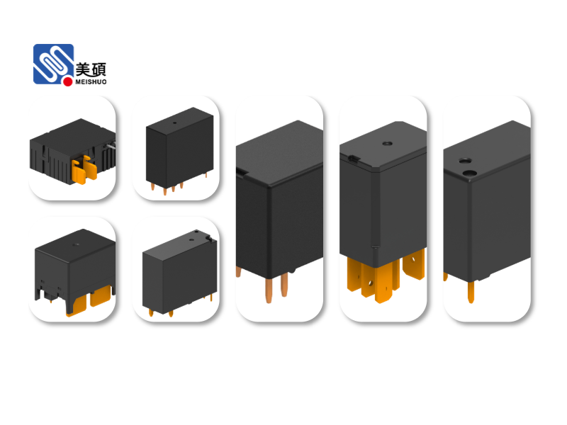
    12V 24V DC Automotive Relay

  • DIN Rail Mount Relay: The Ultimate Guide to Its Applications and Benefits

      The DIN Rail Mount Relay has emerged as a crucial component in modern industrial automation and control systems. This article aims to provide a comprehensive guide to DIN Rail Mount Relays, exploring their applications, benefits, and how they contribute to the efficiency of industrial processes.

      **Introduction**

      DIN Rail Mount Relays are electrical relays designed to be mounted on a DIN Rail, a standardized metal strip used for mounting electrical and electronic equipment in control cabinets. These relays play a vital role in switching electrical currents and voltages in industrial applications, offering reliability, flexibility, and ease of installation. In this article, we will delve into the world of DIN Rail Mount Relays, examining their various types, applications, and advantages.

      **Types of DIN Rail Mount Relays**

      There are several types of DIN Rail Mount Relays, each designed for specific applications:

      1. **Contact Type Relays**: These relays are designed to switch electrical currents and voltages. They come in various contact configurations, such as SPDT (Single Pole, Double Throw), DPDT (Double Pole, Double Throw), and more.

      2. **Solid State Relays (SSR)**: SSRs use solid-state components, like transistors, to switch electrical currents and voltages. They offer several advantages over conventional contact-type relays, such as zero-crossing switching and longer lifespan.

      3. **Miniature Relays**: These relays are compact in size and designed for low current and voltage applications. They are widely used in automation systems and control panels.

      4. **High-Power Relays**: High-power relays are designed for high current and voltage applications, such as motor control and power distribution.

      **Applications of DIN Rail Mount Relays**

      DIN Rail Mount Relays find extensive applications in various industrial sectors:

      1. **Automation Systems**: These relays are extensively used in automation systems for controlling electrical devices, such as motors, sensors, and valves.

      2. **Control Panels**: DIN Rail Mount Relays are ideal for mounting on control panels, allowing easy access to switch electrical currents and voltages.

      3. **Power Distribution**: These relays are used in power distribution systems for controlling and protecting electrical circuits.

      4. **Industrial Equipment**: DIN Rail Mount Relays are used in various industrial equipment, such as CNC machines, robotics, and conveyor systems.

      **Benefits of DIN Rail Mount Relays**

      DIN Rail Mount Relays offer several benefits over traditional relay systems:

      1. **Ease of Installation**: Mounting relays on a DIN Rail is quick and easy, allowing for faster installation and maintenance.

      2. **Space Efficiency**: DIN Rail Mount Relays occupy minimal space, making them ideal for crowded control cabinets.

      3. **Reliability**: These relays are designed for heavy-duty applications, offering high reliability and long lifespan.

      4. **Flexibility**: DIN Rail Mount Relays come in various types and configurations, allowing for customization to meet specific application requirements.

      5. **Safety**: These relays provide electrical isolation between input and output circuits, ensuring safety in industrial environments.

      **Conclusion**

      DIN Rail Mount Relays are essential components in modern industrial automation and control systems. Their versatility, ease of installation, and reliability make them a preferred choice for various applications. By understanding the different types of DIN Rail Mount Relays and their benefits, engineers and technicians can make informed decisions when selecting the right relay for their specific needs.

    DIN Rail Mount Relay

  • Latching Relay 100A: The Ultimate Guide to High-Current Applications

      In today’s rapidly evolving technological landscape, the need for reliable and efficient electrical components has never been greater. One such component that stands out in high-current applications is the Latching Relay 100A. This article aims to provide an in-depth guide to understanding the features, benefits, and applications of this versatile relay.

      The Latching Relay 100A is a type of relay designed to handle high currents, typically up to 100A. Unlike conventional relays that require continuous power to maintain their state, latching relays offer a unique feature of maintaining their position even when power is removed. This makes them ideal for a wide range of applications, including industrial automation, automotive systems, and smart home technologies.

      **Understanding Latching Relay Technology**

      Latching relays operate on the principle of magnetic latching, which is a form of memory effect in ferromagnetic materials. When the relay is activated, the magnetic field creates a magnetic lock that holds the relay in the activated state, even when the power is turned off. To return the relay to its original state, a brief pulse of opposite polarity is required.

      The latching relay 100A is available in various configurations, including normally open (NO) and normally closed (NC) contacts. This allows users to choose the configuration that best suits their specific application requirements.

      **Key Features of Latching Relay 100A**

      1. **High Current Handling**: The Latching Relay 100A is designed to handle high currents, making it suitable for a wide range of industrial and automotive applications.
    2. **Memory Effect**: The magnetic latching feature ensures that the relay maintains its position even when power is removed, eliminating the need for continuous power supply.
    3. **Energy Efficiency**: Since latching relays do not require continuous power to maintain their state, they offer significant energy savings compared to conventional relays.
    4. **Fast Response Time**: Latching relays offer fast response times, allowing for quick and efficient switching operations.
    5. **Robust Construction**: The Latching Relay 100A is built with high-quality materials, ensuring durability and reliability in harsh environments.

      **Applications of Latching Relay 100A**

      1. **Industrial Automation**: Latching relays are widely used in industrial automation systems for controlling high-current loads, such as motors, heaters, and solenoids.
    2. **Automotive Systems**: In the automotive industry, latching relays are used for various applications, including door lock control, fuel pump control, and airbag deployment.
    3. **Smart Home Technologies**: Latching relays are increasingly being used in smart home technologies for controlling high-power appliances, such as lighting, heating, and cooling systems.
    4. **Telecommunications**: In the telecommunications industry, latching relays are used for routing and switching high-current signals in data centers and other communication facilities.
    5. **Medical Equipment**: Latching relays are used in medical equipment for controlling high-current devices, such as patient monitors and life support systems.

      **Conclusion**

      The Latching Relay 100A is a highly versatile and efficient electrical component that offers numerous advantages over conventional relays. Its ability to handle high currents, maintain its state without power, and provide fast response times makes it an ideal choice for a wide range of applications. As technology continues to advance, the demand for such reliable and efficient components is only expected to grow. By understanding the features and benefits of the Latching Relay 100A, engineers and designers can make informed decisions when selecting the right components for their projects.

    Latching Relay 100A

  • The Essential Role of Time Delay Relay (Timer) in Industrial Automation

      The time delay relay, often referred to as a timer, plays a pivotal role in the world of industrial automation. This essential component is designed to introduce a predetermined delay in the switching of an electrical circuit, which is crucial for the smooth operation of various industrial processes. In this article, we will delve into the workings of the time delay relay, its types, applications, and why it is an indispensable tool in the field of automation.

      **Understanding the Time Delay Relay**

      At its core, a time delay relay is an electromechanical device that incorporates a timing mechanism. This mechanism is responsible for introducing a delay between the initiation of the input signal and the activation of the output circuit. The delay duration is pre-set and can range from a few seconds to several minutes, depending on the application’s requirements.

      The primary components of a time delay relay include a set of contacts, an electromagnetic coil, a timing mechanism, and a power supply. When the input signal is activated, the coil energizes, triggering the timing mechanism. During this period, the output contacts remain de-energized, effectively creating a delay. Once the set time elapses, the output contacts change state, allowing current to flow through the circuit.

      **Types of Time Delay Relays**

      There are two primary types of time delay relays: mechanical and solid-state. Mechanical timers utilize moving parts, such as a spring or a flywheel, to create the delay. They are known for their reliability and durability but can be prone to wear and tear over time. Solid-state timers, on the other hand, use electronic components, such as transistors or capacitors, to achieve the timing function. They are generally more compact, energy-efficient, and have a longer lifespan but may be more susceptible to electronic noise.

      **Applications of Time Delay Relays**

      The applications of time delay relays are vast and diverse. Some of the most common uses include:

      1. **Motor Control**: Time delay relays are extensively used in motor control circuits to provide safe and controlled starting and stopping of motors. They can be employed to delay the activation of the motor after a certain period or to prevent the motor from restarting immediately after shutdown.

      2. **Power Distribution**: In power distribution systems, time delay relays help in managing the flow of electricity by introducing delays in the switching of circuits. This is particularly useful in situations where it is necessary to prevent voltage spikes or to allow for the dissipation of inductive loads.

      3. **HVAC Systems**: Time delay relays are often used in heating, ventilation, and air conditioning (HVAC) systems to control the timing of various components, such as fans, compressors, and heating elements.

      4. **Process Control**: In industrial processes, time delay relays are employed to manage the timing of various operations, such as the injection of chemicals, the filling of containers, or the activation of safety features.

      **The Benefits of Time Delay Relays**

      The use of time delay relays in industrial automation offers several benefits, including:

      - **Safety**: By introducing controlled delays, time delay relays help in preventing accidents and ensuring the safety of both personnel and equipment.
    – **Efficiency**: Time delay relays optimize the operation of industrial processes, leading to improved efficiency and reduced energy consumption.
    – **Flexibility**: The adjustable timing feature of time delay relays allows for customization of the delay duration, making them suitable for a wide range of applications.

      In conclusion, the time delay relay is an indispensable component in the field of industrial automation. Its ability to introduce controlled delays in electrical circuits is crucial for the smooth operation of various industrial processes. With its versatility and reliability, the time delay relay continues to be a vital tool in the arsenal of automation engineers and technicians.

    Time Delay Relay (Timer)

  • Understanding the Differences Between 4-Pin and 5-Pin Relays

      Relays are essential components in many electronic devices, acting as switches that control the flow of electricity. Among the various types of relays available in the market, 4-pin and 5-pin relays are particularly popular due to their versatility and reliability. In this article, we will explore the differences between 4-pin and 5-pin relays, their applications, and how to choose the right one for your project.

      **Introduction**

      A relay is an electrical device that uses an electromagnet to open or close circuits. It consists of a coil, an armature, and contacts. When the coil is energized, the armature moves, which in turn closes or opens the contacts. This action allows the relay to control a higher current or voltage than the controlling circuit.

      **4-Pin Relay**

      A 4-pin relay is the most common type of relay. It has four pins: two for the coil and two for the contacts. The coil pins are usually marked as 86 and 85, while the contact pins are marked as 30 and 87. The 86 and 85 pins are connected to the control circuit, and the 30 and 87 pins are connected to the load.

      **5-Pin Relay**

      A 5-pin relay has an additional pin, making it a more versatile option. The additional pin is typically marked as 87a. This extra pin allows the relay to control two separate circuits simultaneously. The 87a pin is connected to the control circuit, and the 30 and 87 pins are connected to the first circuit, while the 85 and 86 pins are connected to the second circuit.

      **Applications**

      4-pin relays are commonly used in applications where a single circuit needs to be controlled. Some examples include:

      - Automotive systems
    – Home appliances
    – Industrial control systems
    – Security systems

      5-pin relays, on the other hand, are ideal for applications that require controlling two circuits simultaneously. Some examples include:

      - Dual-load switching
    – Remote control systems
    – Battery management systems
    – Multi-channel audio systems

      **Choosing the Right Relay**

      When choosing a relay for your project, consider the following factors:

      - **Voltage and Current Ratings**: Ensure that the relay’s voltage and current ratings are suitable for your application.
    – **Contact Material**: Different contact materials have different characteristics, such as durability and resistance to arcing. Choose a contact material that suits your application.
    – **Coil Resistance**: The coil resistance affects the relay’s operating voltage and power consumption. Choose a relay with a coil resistance that matches your control circuit.
    – **Number of Pins**: If you need to control two circuits simultaneously, opt for a 5-pin relay.

      **Conclusion**

      In conclusion, 4-pin and 5-pin relays are both valuable components in electronic devices. Understanding their differences and applications will help you choose the right relay for your project. Whether you need to control a single circuit or two circuits simultaneously, these relays offer a reliable and versatile solution.

    4-Pin / 5-Pin Relay

  • Understanding SPDT / DPDT Relays: Types, Applications, and Benefits

      SPDT / DPDT relays are essential components in electrical and electronic systems, playing a crucial role in signal switching and control. In this article, we will delve into the workings of SPDT and DPDT relays, their applications, and the benefits they offer.

      **Introduction**

      Relays are electromagnetic switches that use an electrical signal to control the flow of a larger electrical current. They are widely used in various industries, including automotive, telecommunications, and industrial automation. SPDT (Single Pole, Double Throw) and DPDT (Double Pole, Double Throw) relays are two types of relays that are particularly useful in complex switching applications.

      **SPDT Relay: Single Pole, Double Throw**

      An SPDT relay has one input (the coil) and three outputs (two common terminals and one normally open terminal). When the coil is energized, it connects the common terminal to the normally open terminal, and when the coil is de-energized, it connects the common terminal to the normally closed terminal. This makes SPDT relays ideal for switching between two circuits.

      **DPDT Relay: Double Pole, Double Throw**

      A DPDT relay has two coils and six terminals (two common terminals, two normally open terminals, and two normally closed terminals). When one coil is energized, it can connect any of the common terminals to any of the normally open terminals, and when the other coil is energized, it can connect any of the common terminals to any of the normally closed terminals. This allows DPDT relays to control two circuits simultaneously.

      **Applications of SPDT / DPDT Relays**

      SPDT and DPDT relays find applications in a wide range of industries and systems:

      1. **Automotive Industry**: SPDT and DPDT relays are used in automotive systems for controlling the operation of headlights, turn signals, and other accessories.
    2. **Telecommunications**: In telecommunications, these relays are used for switching telephone lines, routing calls, and managing network traffic.
    3. **Industrial Automation**: In industrial automation, SPDT and DPDT relays are used for controlling motors, valves, and other actuators.
    4. **Consumer Electronics**: These relays are also used in consumer electronics, such as washing machines, refrigerators, and air conditioners, for controlling the operation of various components.

      **Benefits of SPDT / DPDT Relays**

      The use of SPDT and DPDT relays offers several benefits:

      1. **Reliability**: Relays are highly reliable components, ensuring consistent performance over their lifetime.
    2. **Flexibility**: SPDT and DPDT relays can handle a wide range of voltages and currents, making them suitable for various applications.
    3. **Durability**: These relays are designed to withstand harsh environmental conditions, such as temperature extremes, vibration, and moisture.
    4. **Cost-Effective**: Relays are cost-effective solutions for switching applications, offering a good balance between performance and price.

      **Conclusion**

      SPDT and DPDT relays are versatile and reliable components that play a crucial role in electrical and electronic systems. Their ability to switch between multiple circuits makes them ideal for a wide range of applications. As technology continues to evolve, the demand for high-quality, reliable relays like SPDT and DPDT relays is expected to grow, further solidifying their importance in the world of electronics.

    SPDT / DPDT Relay

  • AC/DC Solid State Relay: A Comprehensive Guide to Its Operation and Applications

      The AC/DC Solid State Relay, a crucial component in modern electrical systems, has gained significant popularity due to its numerous advantages over traditional mechanical relays. This article aims to provide a comprehensive guide to the operation and applications of AC/DC Solid State Relays (SSRs).

      **Introduction**

      An AC/DC Solid State Relay is an electronic device that serves as a switch for alternating current (AC) and direct current (DC) circuits. Unlike mechanical relays that use physical contacts to switch circuits, SSRs use solid-state components like transistors and diodes. This makes them more reliable, efficient, and durable.

      **How Does an AC/DC Solid State Relay Work?**

      The operation of an AC/DC Solid State Relay is based on the principle of solid-state switching. When an input signal is applied to the relay, it triggers a series of electronic components that switch the circuit on or off. The key components of an SSR include:

      1. **Input Circuit**: This circuit receives the input signal and converts it into a form that can be used by the solid-state components.
    2. **Optocoupler**: The optocoupler isolates the input circuit from the output circuit, providing electrical isolation and preventing any interference between the two circuits.
    3. **Output Circuit**: This circuit consists of solid-state components like transistors and diodes that switch the load on or off based on the input signal.

      **Advantages of AC/DC Solid State Relays**

      1. **No Moving Parts**: Unlike mechanical relays, SSRs have no moving parts, which makes them more reliable and durable. This reduces the risk of wear and tear and increases the lifespan of the relay.
    2. **Fast Response Time**: SSRs can switch circuits at a much faster rate than mechanical relays, making them ideal for applications that require rapid switching.
    3. **Electrical Isolation**: The use of optocouplers in SSRs provides electrical isolation between the input and output circuits, which enhances safety and prevents any potential damage due to electrical noise.
    4. **Low Power Consumption**: SSRs consume less power compared to mechanical relays, making them more energy-efficient.
    5. **Wide Operating Range**: SSRs can operate over a wide range of temperatures and voltages, making them suitable for various applications.

      **Applications of AC/DC Solid State Relays**

      AC/DC Solid State Relays find applications in various industries, including:

      1. **Automotive Industry**: SSRs are used in automotive systems for controlling lights, wipers, and other accessories.
    2. **Industrial Automation**: They are widely used in industrial automation systems for controlling motors, pumps, and other electrical devices.
    3. **Home Appliances**: SSRs are used in home appliances like washing machines, refrigerators, and air conditioners for efficient power management.
    4. **Medical Equipment**: They are used in medical equipment for controlling electrical devices like X-ray machines and MRI scanners.
    5. **Energy Management**: SSRs are used in energy management systems for controlling the flow of electricity in buildings and industrial facilities.

      **Conclusion**

      In conclusion, the AC/DC Solid State Relay is a versatile and reliable electronic device that offers numerous advantages over traditional mechanical relays. With its wide range of applications and benefits, SSRs have become an essential component in modern electrical systems. As technology continues to evolve, the demand for AC/DC Solid State Relays is expected to grow, making them an integral part of future electrical systems.

    AC/DC Solid State Relay

  • Contactor and Overload Relay: Understanding Their Functions and Applications

      The world of electrical engineering is vast and complex, with numerous components and devices designed to ensure the safe and efficient operation of electrical systems. Two such critical components are the contactor and the overload relay. This article aims to provide a comprehensive understanding of these devices, their functions, and their applications in various industries.

      **Introduction**

      Electrical systems are integral to modern life, powering everything from homes to industrial plants. The proper functioning of these systems relies on the use of various electrical components, each serving a specific purpose. Among these components, the contactor and the overload relay stand out for their crucial roles in protecting and controlling electrical circuits.

      **What is a Contactor?**

      A contactor is an electrical switch used to control the flow of electrical current in a circuit. It is designed to handle high currents and is commonly used in industrial applications. Contactors are electromechanical devices that use an electromagnet to open and close contacts, thereby controlling the circuit. They come in various types, including single-phase and three-phase contactors, and are available in different sizes and ratings to suit different applications.

      **Functions of a Contactor**

      The primary functions of a contactor include:

      1. **Circuit Control**: Contactors are used to switch on and off electrical circuits, allowing for the control of electrical equipment such as motors, transformers, and lighting systems.
    2. ** overload Protection**: Some contactors are equipped with overload protection features, which help prevent damage to the connected equipment in case of excessive current flow.
    3. **Remote Control**: Contactors can be controlled remotely, making them ideal for applications where manual switching is not feasible or safe.

      **What is an Overload Relay?**

      An overload relay is a protective device used to monitor the current flowing through an electrical circuit and trip the circuit in case of excessive current. It is designed to protect motors and other electrical equipment from damage due to overloading or short circuits.

      **Functions of an Overload Relay**

      The primary functions of an overload relay include:

      1. **Overload Protection**: Overload relays monitor the current in a circuit and trip the circuit in case of excessive current, preventing damage to the connected equipment.
    2. **Short Circuit Protection**: Overload relays can also detect short circuits and trip the circuit, protecting the equipment and preventing fires.
    3. **Motor Protection**: Overload relays are commonly used to protect motors from damage due to overloading, phase loss, and unbalanced loads.

      **Applications of Contactor and Overload Relay**

      Contactor and overload relay combinations are widely used in various industries, including:

      1. **Manufacturing**: In manufacturing plants, contactors and overload relays are used to control and protect motors and other electrical equipment.
    2. **Construction**: In the construction industry, these devices are used to control and protect electrical systems in buildings and infrastructure projects.
    3. **Transportation**: Contactors and overload relays are used in transportation systems, such as electric trains and buses, to control and protect electrical equipment.

      **Conclusion**

      In conclusion, the contactor and the overload relay are essential components in electrical systems, providing control and protection to ensure the safe and efficient operation of electrical equipment. Understanding their functions and applications is crucial for anyone working in the field of electrical engineering or related industries.

    Contactor and Overload Relay

  • Signal Relay (Telecom): The Unsung Hero of Modern Communication

      Signal relay, a term often overlooked in the vast landscape of telecommunications, plays a pivotal role in the seamless transmission of information across vast distances. This article delves into the world of signal relay in telecom, exploring its significance, functioning, and impact on modern communication.

      The Evolution of Signal Relay

      To understand the importance of signal relay in telecom, it is crucial to look back at its evolution. The concept of signal relay dates back to the early days of telegraphy, where messages were transmitted through a series of relay stations. These stations were responsible for amplifying and forwarding the signals to ensure they reached their intended destination.

      As technology progressed, the telegraph was replaced by the telephone, and the need for signal relay persisted. With the advent of radio communication, signal relay became even more critical, as it allowed for the transmission of voice signals over long distances.

      How Signal Relay Works

      Signal relay in telecom involves the process of amplifying and forwarding signals to maintain their integrity and strength as they travel through the communication network. This process is essential because signals naturally weaken over distance, leading to degradation in quality and potential loss of information.

      The primary components of a signal relay system include:

      1. Transmitters: These devices generate the original signal, which can be in the form of voice, data, or video.

      2. Receivers: These devices capture the transmitted signal and convert it into a format that can be processed or amplified.

      3. Amplifiers: These devices increase the strength of the signal, ensuring it remains strong enough to travel through the communication network.

      4. Repeaters: These devices receive, amplify, and retransmit the signal, effectively extending its range.

      5. Antennas: These devices transmit and receive the signals, acting as the interface between the relay system and the environment.

      The Impact of Signal Relay on Modern Communication

      Signal relay in telecom has a profound impact on modern communication, making it possible for us to connect with people across the globe in real-time. Here are some key benefits of signal relay:

      1. Extended Range: Signal relay allows for the transmission of signals over long distances, enabling global communication.

      2. Improved Signal Quality: By amplifying and forwarding signals, signal relay ensures that the quality of communication remains high, even over long distances.

      3. Enhanced Reliability: Signal relay systems are designed to be robust and reliable, minimizing the risk of signal loss or degradation.

      4. Cost-Effective: Signal relay systems are cost-effective, as they utilize existing infrastructure and do not require the construction of new communication lines.

      5. Versatility: Signal relay can be used in various communication systems, including telephony, radio, and satellite communication.

      Challenges and Future Developments

      Despite its numerous benefits, signal relay in telecom faces several challenges. One of the primary challenges is the increasing demand for higher data rates and bandwidth, which requires more advanced and efficient relay systems.

      To address these challenges, researchers and engineers are working on several cutting-edge technologies, such as:

      1. MIMO (Multiple Input, Multiple Output): This technology allows for the simultaneous transmission of multiple signals, increasing the overall capacity of the communication network.

      2. mmWave (Millimeter Wave) Communication: This technology operates at higher frequencies, offering greater bandwidth and potential for higher data rates.

      3. 5G and Beyond: The rollout of 5G networks is expected to revolutionize signal relay in telecom, with its ability to support massive machine-type communication and ultra-low latency.

      In conclusion, signal relay in telecom is an unsung hero that enables us to communicate seamlessly across vast distances. As technology continues to evolve, signal relay will undoubtedly play a crucial role in shaping the future of modern communication.

    Signal Relay (Telecom)

  • Power Relay 30A/40A: A Comprehensive Guide to High-Current Relay Applications

      The Power Relay 30A/40A is a crucial component in various industrial and commercial applications, particularly where high current handling capabilities are required. In this article, we will delve into the features, applications, and benefits of this high-performance relay.

      **Introduction**

      Relays are essential in electrical systems, serving as switches that control the flow of electrical current. The Power Relay 30A/40A is designed to handle high currents, making it ideal for applications that demand robust and reliable switching. In this guide, we will explore the key aspects of the Power Relay 30A/40A, including its specifications, advantages, and common applications.

      **Key Features of Power Relay 30A/40A**

      1. **High Current Handling Capacity**: The Power Relay 30A/40A is capable of handling currents up to 30A and 40A, respectively. This makes it suitable for applications that require the control of high-powered circuits.
    2. **Robust Construction**: The relay is designed with a durable construction, ensuring long-term reliability and resistance to wear and tear.
    3. **Multiple Contact Arrangements**: The Power Relay 30A/40A offers various contact arrangements, allowing for customization to meet specific application requirements.
    4. **Wide Operating Voltage Range**: The relay can operate within a wide range of voltages, making it versatile for different electrical systems.
    5. **Low Power Consumption**: Despite its high current handling capacity, the Power Relay 30A/40A consumes minimal power, contributing to energy efficiency.

      **Applications of Power Relay 30A/40A**

      1. **Industrial Automation**: The Power Relay 30A/40A is widely used in industrial automation systems for controlling high-powered motors, solenoids, and other devices.
    2. **Power Distribution Systems**: These relays are employed in power distribution systems to switch high currents, ensuring the safe and efficient operation of electrical networks.
    3. **HVAC Systems**: In heating, ventilation, and air conditioning (HVAC) systems, the Power Relay 30A/40A is used to control high-powered fans and compressors.
    4. **Vehicle Electrical Systems**: The relay finds applications in vehicle electrical systems, such as controlling high-powered accessories and ensuring the safety of the electrical system.
    5. **Solar Power Systems**: In solar power systems, the Power Relay 30A/40A is used to switch high currents in solar panels and inverters.

      **Benefits of Using Power Relay 30A/40A**

      1. **Reliability**: The Power Relay 30A/40A offers high reliability, ensuring uninterrupted operation in critical applications.
    2. **Efficiency**: The relay’s low power consumption contributes to energy efficiency, reducing operational costs.
    3. **Versatility**: The wide operating voltage range and various contact arrangements make the Power Relay 30A/40A suitable for a diverse range of applications.
    4. **Longevity**: The durable construction ensures a long service life, minimizing maintenance and replacement costs.

      **Conclusion**

      The Power Relay 30A/40A is a reliable and efficient solution for high-current applications. Its robust construction, high current handling capacity, and versatility make it an ideal choice for various industrial and commercial applications. By understanding the key features and benefits of this relay, you can make an informed decision when selecting the right relay for your specific needs.

    Power Relay 30A/40A